
Joy Technology Co.,Limited
SMT Equipment∣SMT parts∣SMT Solution provider


1) Purpose
Proper operation of the fully automatic press ensures that the machine is operating properly, thus ensuring product quality.
2) Scope of application
Manufacturing Department Production Workshop SMT Line
3) noun explanation
Solder Paste Printing Machine: Modern solder paste printing machine is generally composed of plates, tin paste, embossing, and transmission board. Its working principle is: firstly, the circuit board to be printed is fixed on the printing positioning table, and then the solder paste or the red glue is printed on the corresponding pad through the steel mesh by the front and rear scrapers of the printing machine, and the PCB which is uniformly printed is passed through. The transfer station is input to the placement machine for automatic placement.
4) duties
4.1 The equipment engineer is responsible for the maintenance and periodic maintenance of the press.
4.2 The equipment technician is responsible for the production and modification of the printing press program.
4.3 The operator is responsible for the operation and daily maintenance of the printing press.
4.4 The production supervisor is responsible for supervising the implementation.
5) management regulations
5.1 Check before booting
5.1.1 Confirm that the appearance of the machine is clean and confirm that there is no debris in the inside of the equipment, especially in the range of the running track.
5.1.2 Confirm that the working environment temperature is between 23±5°C and the humidity is <80%.
5.1.3 Determine the working pressure of the equipment is between 0.4 and 0.6 MPa.
5.1.4 Confirm that the equipment power supply and related cables are normal.
5.2 boot
5.2.1 Turn on the power of the device.
Equipment power supply
5.2.2 After the device is booted, enter the zeroing interface, click [Start Zero], and wait for zero to complete.
Device zeroing interface device zeroing completion interface
5.3 call the production program
5.3.1 According to the system prompt, select the program permission, the operator does not need to enter the password, and the rest must enter the corresponding password to obtain the permission. Click Back when done.
Privilege selection interface
5.3.2 Click the [Open Project] option on the main interface to select the corresponding production program, such as BCLG4A-V05.
Main interface Figure 6. Caller interface
5.3.3 After the selection is completed, it will automatically return to the main interface, and the program is already open.
Click [Data Entry] to confirm the printing parameters of the product to be produced.
Data entry first page
5.4 installation of steel mesh
5.4.1 After confirming the first step data, click Next to enter the second page, and the press prompts to adjust the track width. Before adjusting the width, confirm whether there is a top plate/thimble on the platform, and then remove it. Reinstall after the width adjustment is completed. The top plate should be installed as close as possible to the track, between the tracks 1-2CM but not touching the track to prevent the track from being worn and deformed. If the thimble is to be installed, the bottom element should be avoided to prevent the collision. Click the [Auto Positioning] option, and the press will move the CCD lens and set the board into the board.
Adjust the transport track
CCD lens and access panel
5.4.2
The PCB is fed from the press exit and the press will complete the automatic positioning. At this point, the PCB should be about 0.5mm above the track.
PCB positioning
5.4.3
Select the corresponding number of steel mesh (such as BCLG4A-V05) according to the type of machine to be produced. Then select [Z-axis up], place the stencil into the frame support plate and clamp it. Adjust the position of the PCB pad and the stencil opening. The Y direction can be fine-tuned by the device, and the X direction is finely adjusted by hand. After the adjustment is completed, click [Frame Fixed Valve] and confirm that the steel mesh has been clamped. Click [OK] to complete the installation of the steel mesh.
Steel mesh installation
5.5 Install the scraper and add solder paste
5.5.1 Place the two scrapers on the scraper seat and lock them. Shake the scraper by hand to confirm the installation effect.
5.5.2 Click the [Print from Back] button at the top of the main interface to move the scraper backwards. Add the solder paste that has been thawed to the steel mesh. The width of the solder paste should be slightly larger than the width of the stencil opening and smaller than the width of the scraper. A missing print has occurred. Click the [Print from the front] button at the top of the main interface to move the scraper to the front of the solder paste.
Solder paste width
5.6 printing effect check
5.6.1 Click the [Start] button on the right side of the main interface, and according to the prompt, the PCB on the track will be transmitted out and re-introduced into the new PCB. The device will automatically align the steel mesh according to the previous set value, and prompt the device to fine tune before printing.
5.6.2 Device fine-tuning mode The Z-axis platform drives the PCB to perform four-way fine adjustment. Click [+] in the left and right direction of the mobile PCB, and [-] in the right and down directions.
Printing fine-tuning
5.6.3 After the debugging is completed, click [OK] and the device will automatically print. After the printing is completed, the printing effect is manually checked. If it is qualified, click the [No More] button in the fine-tuning interface before the next printing, and enter the automatic printing mode. If it is not qualified, repeat the fine adjustment until it is qualified.
5.7 automatic printing
5.7.1 The operator should check the printing effect of the top 10 PCS.
5.7.2 The press will prompt to add solder paste every 50 PCS, and the operator will confirm if it needs to be added. After the confirmation is completed, the printing effect of the continuous 5PCS is checked and recorded in the "SMT Printing Quality Checklist".
5.7.3 Automatic cleaning of the steel mesh every 3~5 PCS, the specific frequency can be fine-tuned according to the PCB board. Manual cleaning is not possible if the device cannot be used for automatic cleaning. The cleaning method is to use a clean cloth to wipe back and forth at the bottom of the steel mesh.
5.7.4 Manual cleaning must be performed after 4H of continuous operation of the equipment. For manual cleaning, the steel mesh and the scraper should be removed, and the alcohol and the dust-free cloth should be used for cleaning. After the cleaning is completed, the air gun is used to blow away the debris on the back side to prevent the steel mesh blocking hole from affecting the solder paste printing effect.
5.8 End production
5.8.1 After the production is completed, press the START/STOP button on the device, then click [Stop] at the bottom of the production interface to complete the printing operation as prompted.
.stop producing
5.8.2 Click the [Manual Cleaning] button to return the scraper to prevent collision when the solder paste is collected. Use the ink knives to reclaim the remaining solder paste on the steel mesh into the solder paste bottle, then remove the scraper and recycle the solder paste remaining on the scraper into the solder paste bottle. Finally, click [steel mesh release] to remove the steel mesh. After the cleaning is completed, the steel mesh is returned to the steel mesh frame.
Manual cleaning
5.8.3 Remove foreign objects in the operating range of the stencil support plate and other moving mechanisms to prevent equipment failure.
5.8.4 Click the Exit button on the main interface, the device software will be closed at the same time as the operating system, and finally the main power switch will be turned off.
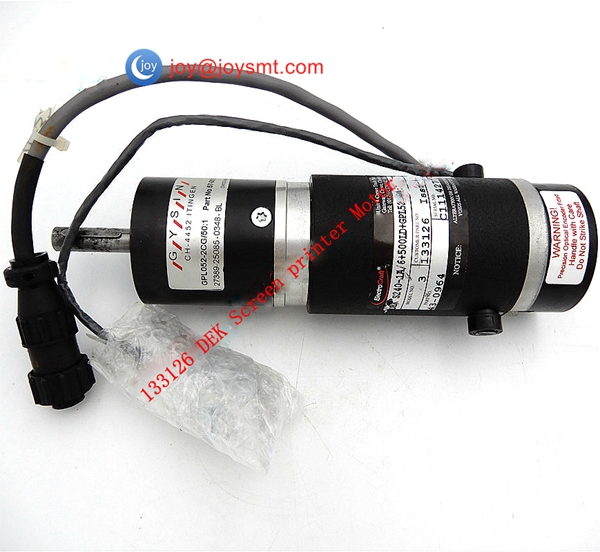
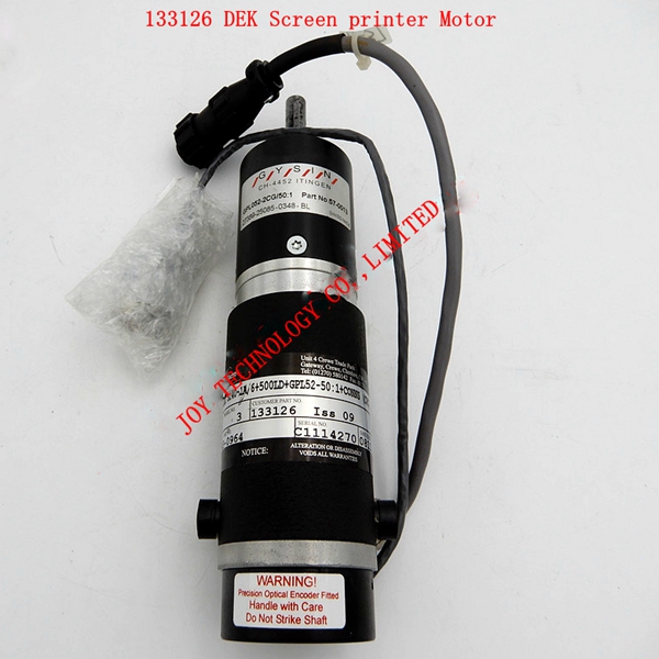
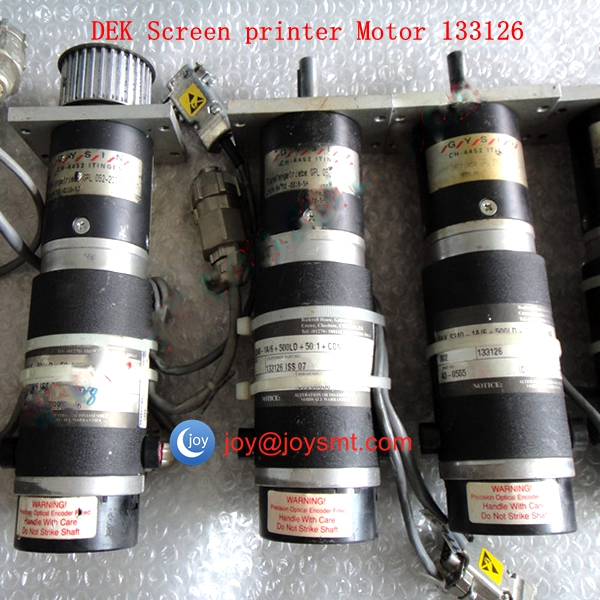
JOY TECHNOLOGY Can also supply other DEK parts List as follows:
DEK VISION Y AXIS SERVO MOTOR 133128/160706/145520 D-160706/D-145520/ D-133128
DEK TABLE RISING SERVO MOTOR 160708/140737/ D-160708/D-140737
DEK VISION X AXIS SERVO MOTOR 133127/160704/145817 D-160704/D-145817/ D-133127
DEK RAIL MOTOR 157729/157731 D-157729/D-157731
DEK PAPER CLEAN MOTOR 181452/157373/129352/D-181452/D-157373/D-129352
DEK BOM CAMERA ASSY GREEN 145550 (compatible 155826 181501 181322)
DEK BOM CAMERA ASSY GRAPHITE 2Q 181322(compatible 145550 155826 181062)
DEK ACTUATOR LEADSCREW ASSY 158472
DEK PROCESSOR BOARD COMPLETE (INFINITY) 159224
DEK SINGLE BOARD COMPUTER (ADVANTECH T-PCA6180E2002) 181009/160947
DEK PROCESSOR CARD (386 SX,8 MB) 140069
DEK PROCESSOR BOARD(486 8MB RAM 100MHz) 137325
DEK REAR/FRONT SQUEEGEE MOTOR 155806/155804 /D-155806/D-155804
DEK MODIFIED LEAD SCREW(ROLLER ACTUATOR) 158472/D-158472
DEK CPU CARD 159224/160992/181009/159198/160947/D-159224/D-160992/D-181009/D-159198/D-160947
DEK PC CONTROLLER ICL ROHS COMPLIANT 191022/191543
DEK TORQUE AMP ASSEMBLY BOM 153073
DEK EUROAMP 10 CARD UL 114025
DEK CARD EXPANSION FIREWIRE UNIBRAIN 191015/D-191015
DEK PC SPARE PSU IBUS PC 190722
DEK PC POWER 190696/D-190696
DEK BOM BOARDSTOP KIT LIP SEAL 183961
DEK CYLINDER 4 STROKE 20 BORE 165675
DEK BOM BOARDSTOP KIT LIP SEAL 193377
DEK MODIFIED CYLINDER (FROM 107460) 107850
DEK ASSY BOARD CLAMPS QUICK RELEASE 250MM 178031
DEK 145817 CAMERA X MOTOR
DEK 145014 EUROSTEP CONTROLLER
DEK 140472 RAIL MOTOR
DEK 140376 ACTUATOR MOTOR
DEK 133127 X CAMERA MOTOR
DEK 125459 NEXTMOVE CARD ( TXT )
DEK 114025 EUROAMP 10 CARD UL
DEK 191088 SOLVENT PUMP 183390 |183227
DEK 107682 STEP DRIVE PCB GRADE FR4 LAMINATE PVP134
DEK MOTOR 181425 MAXON 265998
DEK 140737 RISING TABLE SERVO MOTOR GR80x80
DEK 185253 CONTROLLER NEXT MOVE ES
DEK NODE 3 PRINT CARRIAGE 181471
181436 DEK MAIN IO NODE
DEK 265GSX 107688 PCAD12 BOARD
DEK 256 GSX CARD 145015 EUROSTEP CONTROLLER
DEK 145009 265 GSX LT VISION BOARD VPM 5238-32D
183961 DEK Baffle Cylinder BOM BOARDSTOP KIT LIP Seal 193377
DEK-107298-BEARING-CAPD
DEK 195194 Button SWITCH SAFETY OMRON ESTOP
DEK 1394 Camera Signal Cable 193408
DEK 193377 Board Stop CYLINDER
Dek 193377 Bom Boardstop Kit Lip Seal CD85n12 0017 Cfk00146
DEK 191015 Card Expansion Firewire Unibrain
DEK 188682 X Axis Belt
DEK D-188759 CASSETTE TYPE M
DEK 185934 Belt
183390 DEK Alcohol Pump EMX08-T/C 191088 183227 111895
DEK 119203 Board Clamp
DEK 129352 | 181452 Motor and Gearbox
DEK Belt 145099
DEK 145518 X Axis Timing Belt
DEK 156028 X Axis Tanks Chain
DEK 165520 Belt
DEK WIREROPE 177055 BOM CABLE CRIMPED ASSEMBLY RAILS ASM
DEK 183388 SENSOR PHOTOELECTRIC DIFFUSE FHDK 14N5101 S35A
156220 LEADSCREW END NUT
156219 MOTOR SUPPORT PLATE
156200 REAR SQUEEGEE FOOT
156199 FRONT SQUEEGEE FOOT
156195 SPLINE SUPPORT BLOCK
156192 BALL SPLINE
155806 STEPPER MOTOR, REAR
155804 STEPPER MOTOR, FRONT
155792 PRESSURE AMP LOOM
155786 SQY'S HOME LOOM BOM
146226 SQY LOAD CELL AMP
145686 BEARING, ANGULAR CONTACT
140327 SOLID STATE PUSH BUTTON SWITCH
112545 DOWEL 3DIA X 12LG GRD 1
112414 CABLE TIE CLAMP
156721 CABLE TIE, SCREW MOUNTED
156590 T-SLOT NUT, SIZE 8, M8
156589 ADAPTER SIDE SUPPORT, LH
156586 SPACER DISK
156580 CYLINDER BRACKET
156513 SCREEN DEPTH ADJUST. 248/249/260
156478 BRACKET
156460 CHASE ADAPTER ARM, LH
156410 CHASE ADAPTER ARM, RH
156409 CHASE ADAPTER, CASTING
B0059 BEARING DGBB SSL1680ZZ
700817 SCREW, CONE POINT M4x5 SKT SET
If there is no matching model of DEK Parts,pls contact us directly.
JOYSMT have good source & large stocks for major brand SMT Parts and Equipment.
Such as SMT nozzle | nozzle holder | nozzle shaft, SMT feeder|SMT feeder parts|Feeder calibartion jig,
Laser ,Sensor, Servo Motor, Servo Driver, Controller Board Card, Solenoid valve,Ejector, Ball screw,
SMT Belt, Cable, SMT Filter, SMT consumable Material etc.
 Panasonic CM202 CM402 CM602 NPM Nozzle 110 115 KXFX0383A00
 Samsung SM320 IC tray
 YAMAHA FEEDER CALIBRATION JIG