Joy Technology Co.,Limited

SMT Equipment∣SMT parts∣SMT Solution provider

joy@joysmt.com

joysmt maintenace center

Technique & Support

Location  : Home > Service> Technique & Support

Miniaturization with Help of Reduced Component to Component Spacing

Time:2016-06-08    Source:www.joysmt.com

Miniaturization with Help of Reduced Component to Component Spacing

Miniaturization with Help of Reduced Component to Component Spacing


Miniaturization and the integration of a growing number of functions in portable electronic devices require an extremely high packaging density for the active and passive components. There are many ways to increase the packaging density and a few examples would be to stack them with Package on Package (PoP), fine pitch CSP’s, 01005 and last but not least reduced component to component spacing for active and passive components.

The use of fine pitch CSP, PoP component’s and 01005(Imperial) poses a number of challenges for PCB Design, SMT Assembly process and reliability and by placing them closer together many of these challenges will be magnified. A feasible assembly process must be achieved. The assembly process ranges all the way from screen-printing, placement and reflow soldering in air or nitrogen.Many factors influence the quality of the assembly process and with the reduced pitch and component spacing, the process capabilities for both assembly and PCB fabrication will be tested to its limit and beyond.

In many cases these assemblies also require a rework process either in the manufacturing facility or at repair centers when the product fails in the field during usage. In addition the correct materials such as PCB material, PCB surface finish, solder paste, dipping flux and PCB design need to be selected to ensure high yielding, cost effective and reliable interconnects. Of course, the mechanics of the products makes a big difference as well but it is very product dependent. Many of today’s products leave little room for designing the mechanics in the most reliable way due to total cost and overall look and size of the products.

This paper will discuss different layouts, assembly and material selections to reduce component to component spacing down to 100-125um (4-5mil) from today’s mainstream of 150-200um (6-8mil) component to component spacing.

Miniaturization with Help of Reduced Component to Component Spacing


With the never ending drive for smaller lighter and more advanced features on portable products, the ability to handle miniaturization is becoming a key capability to enable these requirements. Miniaturization can be done in many ways and this paper touches on the assembly technologies that can be incorporated in a more or less standard surface mount assembly line with minimal equipment and material upgrades.

Before starting any development work it is critical to understand product and industry requirements and capabilities. If this is not fully understood no development activities can start. PCB fabrication can be seen as a good example on the importance of understanding requirements and capabilities. If a good quality PCB can’t be sourced within the scope of the assembly development project there is no reason to develop an assembly technology process since there is not anything to do the assembly development work on. The key is to ensure that several options for assembly can be achieved and this should be seen as a “toolbox of technologies”.

For the active components die stacking inside a package is one common way to increase the functionality per unit area on a PCBA, which is very popular for memory devices. However, there can be some drawbacks to creating a stacked die solution. First, this method is a customized solution. If any of the dies to be used changes, the die stack needs to be evaluated to see if changes are needed in the package. For example, a die shrink may occur and this could change the whole package structure. Secondly, if one or more of the dies inside the package fail, the whole unit will have to be scrapped, which would lead to increased cost; this is the well-known “compounded yield” issue. Lastly, trying to coordinate the many semiconductor suppliers to provide dies to a packaging house for die stacking can be a challenging task and overall responsibility for the complete package yield could in some cases be unclear.

In the PoP process one component is placed on top of another package during a single SMT process to fully utilize the three dimensional aspect of the product. The topside of the bottom component has pads similar to the pads on the PCB for attachment of the top package. Each package is a single unit that can be fully tested as a normal IC package is done today, so the yield would be comparable to the normal yield commonly seen today. Another advantage would be the ability to have second source options that could be fairly easily inserted into the process. The stacked package can be processed in a traditional SMT environment with a few upgrades that are readily available. Therefore, package stacking enables configurable assemblies and provides greater flexibility in the supply chain. It can be used for memory applications or for a processor with memory, with faster time to market and better management of package testing and compounded yield issues.

Reduced pitch is without doubt one of the bigger challenges for the active components, but it is a very effective way to achieve miniaturization. Today mainstream is 0.4mm pitch, but 0.3mm pitch is getting more and more popular. Taking the step to 0.3mm from 0.4mm poses a number of challenges mainly related to PCB design, screen printing and getting good quality PCBs. For 0.3mm pitch our studies show that screen printing is a big challenge and a dip fluxing process might be needed for some applications. This might sound like a big change, but the process for running an in-line flip chip or Package on Package process is more or less in place since many production lines are already using this process.

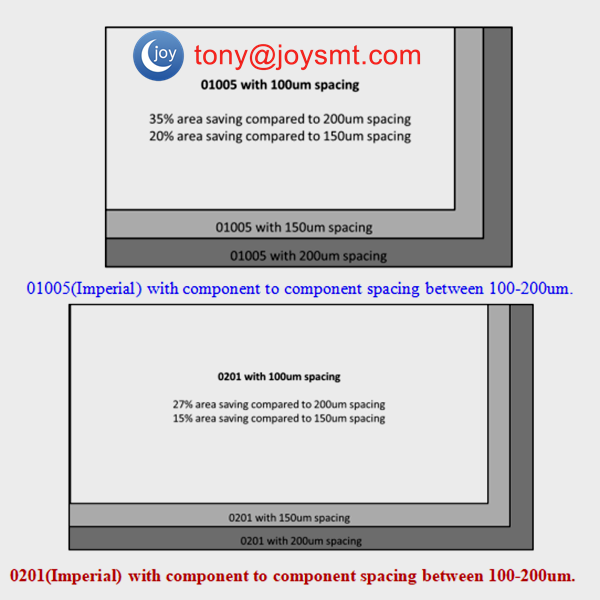
With regards to passive components, two very effective ways to achieve miniaturization include using smaller parts such as 0201(Imperial) and 01005(Imperial) and reducing component to component spacing. Both strategies are very much feasible, but each needs to be carefully considered with the help of analyzing process data and total cost. Considering the extreme drive for miniaturization and added functionality, it is not surprising that the 01005(Imperial) packages are becoming increasingly used despite the limited electrical values currently available, the relatively high component cost and the difficulties in the production processes. With reduced component spacing from 0.2mm down to 0.1mm an up to 35% area saving can be achieved (Figures 1-2) and by moving from 0402(Imperial) to 01005(Imperial) with 150um component spacing a 74%  can be achieved.


To understand what technologies and capabilities that are required going forward it is key to have a well established roadmap process that captures product and industry requirements and availability of components. PCB and materials are equally important. The technology roadmap process typically has four major process steps and each of them is equally important:

Technology Requirement
Technology Roadmap
Technology Development
Technology Deployment

Test Vehicles and Materials
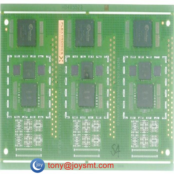
The process development and factory qualification test vehicle for miniaturized assembly technologies (Figure 4) is designed to be similar to a cellular phone using the IPC drop test vehicle JESD22-B111 as a baseline. The company test vehicle is continuously being upgraded based on new findings and technologies; it also serves as a verification vehicle for the “Printed Circuit Board Design Guidelines”.

The PCB panel is 132mm x 77mm in size (Figure 4) and it is made with three identical sections. The surface finish for this board is Organic Surface Preservative (OSP). One side of the PCB is using Solder Mask Defined (SMD) pads and the other side is using Non Solder Mask Defined (NSMD) pads for the active components. The PCB has four layers using halogen- free Resin Coated Copper (RCC) in the outer layers to enable a better quality for the microvia drilling. Halogen-free FR4 is used in the inner layers. The total PCB thickness is 0.788mm

Miniaturization with Help of Reduced Component to Component Spacing

Due to the high I/O count, small pad sizes and tight spacing the PCB design is very challenging in many aspects.
•1/2Oz (20um copper), around 33-34um (after plating)
•50um copper/copper spacing (inner and outer layers)
•50um solder mask slivers
•25-40um solder mask registration tolerance
•60um uvias.
•0.2mm uvia capture pads in outer and inner layers.
No silkscreen is used to prevent screen printing issues. Typical silkscreen thickness is around 20um

Copper filled microvias are used based our previous studies on 0.3-0.4mm pitch CSPs where we see better screen printing results since the solder paste has a bigger area to adhere against. Furthermore, the so called microvia induced voids more or less disappear on bumped connections such as CSPs and BGAs. The negative impact of copper filled microvias is increased PCB price.

The PCB includes a number of different component type’s including;
Passive parts (Imperial): 01005, 0201, 0402, 0603 and 0805.
Active parts: 0.4mm pitch PoP, 0.4mm pitch CSP and 0.3mm pitch CSP.

The PCB has different sections with various component spacing within the same component type, and with mixed component types, the spacing ranges between 100-200um. Due to the narrow component and pad spacing, solder mask between the pads is only feasible down to 150um pad to pad spacing.

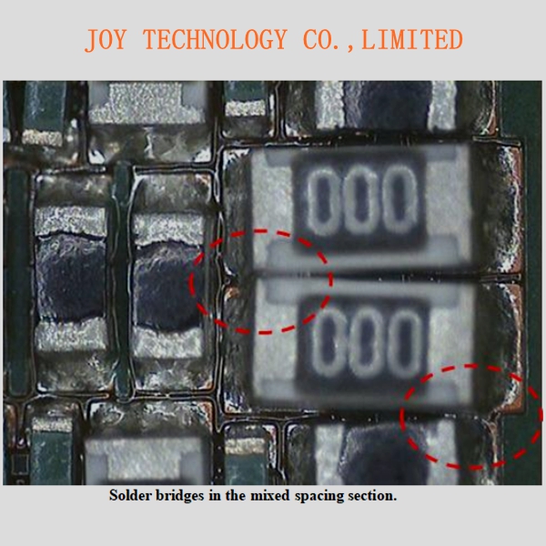
The main focus on this study have been to reduce the component spacing between passive parts since this is the main challenge due to solder bridges. Passive components next to CSP’s and CSP’s next to CSP’s present minor assembly issues and rework concerns.


Solder Paste selection
A type 4 SAC 305 (Sn96.5Ag3Cu0.5) halogen-free solder paste was used for all our studies related to miniaturized assembly technologies. The selection of solder paste was done through extensive evaluations on printability, voiding, slumping, solder balling, wetting and SIR (surface insulation resistance). For all technologies included on the miniaturized test vehicle the common challenge is solder paste printing and the 0.3mm pitch CSP and 01005 (Imperial) locations use very similar apertures sizes.

Assembly Details
Assembly trials were conducted under controlled production environment. During the assembly trials, dip fluxing was used for the PoP and 0.3mm pitch CSPs that were mounted on the board as well. All components were mounted at high speed to simulate a true production environment.

Paste Printing and Solder Paste Inspection

A standard paste printing process was used with a 3mil (75um) and 4mil (100um) thick laser-cut stencil which was electro- polished from a local supplier in Asia where most of the production of miniaturized products would be produced. Automated solder paste inspection was done on all locations to collect data and automatic stencil cleaning was done after each print mainly due to the 01005 (Imperial) and 0.3mm pitch CSPs. In true production the cleaning frequency could potentially be reduced but this would be product dependent. The solder paste volume criteria were set to 40-120% of the theoretical value.

Using a 3mil (75um) stencil gives a much higher Pp and Ppk compared to a 4mil (100um) stencil (Figure 6) and this is expected due to an Area Ratio (AR) of 0.5 with a 4mil (100um) stencil and 0.66 with a 3mil (75um) stencil.

All solder paste deposits with a 3mil (75um) stencil were within specification showing 0 DPMO print failures. The solder paste printing with a 4mil (100um) stencil showed a DPMO of 1382 on 01005 (Imperial) but these PCBs were still assembled and the solder joints still met IPC 610E standard with regards to solder joint quality.

Pick and Place details
All the assemblies were done on standard fine pitch surface mount machines equipped with an accuracy of 40um at 3 Sigma. The flux dipping unit used was the linear dipping unit which comes with replaceable dipping plates. No assembly related defects were detected during for the 0.3mm pitch CSP or 0.4/0.4mm pitch PoP components once the correct process parameters were set.

Reflow
A standard lead-free reflow profile was used. The reflow was done in Air and Nitrogen, with 65 seconds above 217ºC and 245ºC peak temperature. Our previous studies on 01005 (Imperial) showed that a fast ramp of 1.0 ºC/s and above between 180-217 ºC gives better wetting when reflowed in air but the same basic process was used both for the air and nitrogen reflow in this study. Graping/Incomplete wetting is a clear sign of too slow a ramp between 180-217 ºC


Rework Process
Rework becomes more challenging with reduced component to component spacing, but if the process is setup correctly the amount of rework should be at a minimum. A standard rework process was used for all components on the PCB. For the passive components manual rework was done with help of fine tip tweezers and a hot air blower. For the CSP and PoP a “BGA repair” machine was used.

Results
The DPMO values (Figure 8) show a very clear breakpoint between 100-125um component to component spacing and it is also shown that the stencil thickness has a major impact at the smaller component to component spacing but that the breakpoint is the same. The usage of nitrogen shows no impact with regards to spacing DPMO.


During cross-sectioning and visual inspection of the air reflowed samples it was noticed that some of the 0.4mm pitch PoP components showed “head-on-pillow” and that the solder joint did not wet the whole pad. This was expected and proven in earlier builds, but it was decided to still run in air reflow to be able to validate potential spacing differences between air and nitrogen reflow. The samples reflowed in nitrogen did not show any issues for the 0.3mm pitch CSP and PoP components.


For the 01005 (Imperial) components the wetting is not as good in air reflow compared to nitrogen reflow but still considered as acceptable according to IPC-610 E standard.

Conclusions
There are many ways to achieve miniaturization and the key is to have a “toolbox of technologies” to be able to fulfil various requirements. Depending on the product several options can be considered and the selection should be based on data and not assumptions. It is important to consider the interaction between multiple technologies in all areas during development and deployment since several advanced technologies will, in most cases, be used on the same product. Based on our studies, 125um component to component is feasible with both a 75um and 100um stencil thickness. At 100um component to component spacing a 4mil (100um) stencil is not acceptable, but despite a DMPO of around 370 with a 3mil (75um) stencil, this can in some cases be acceptable.


Joy Technology Co.,Limited

Copyright © 2012-2023 Joy Technology

Office address: Building D,Guosheng industrial Park,Dalang street,Longhua district,Shenzhen,China

Factory address:,Wanfeng Innovation Technology Park, No.1048 Shatou,Chang'an town, Dongguang city,Guangdong province